
Henry
Definition: The meter-kilogram-second unit of inductance, equal to the inductance of a circuit in which an electromotive force of one volt is produced by a current in the circuit which varies at the rate of one ampere per second.
Related Links
Henry (unit) – Wikipediahenry (unit) – Simple English Wikipedia, the free encyclopedia
What is henry (H)? – Definition from WhatIs.com
Henry | unit of inductance | Britannica.com
Henry (unit)
Related Videos
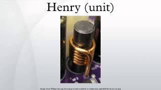
Henry (unit)
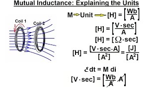
Physics - E&M: Inductance (2 of 20) Mutual Inductance: Explaining the Units
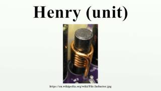
Henry (unit)
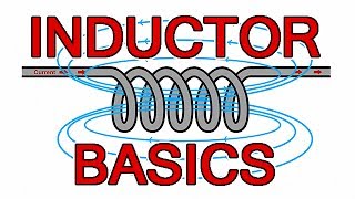
Inductor basics - What is an inductor?
-
Henry (unit)
-
Physics - E&M: Inductance (2 of 20) Mutual Inductance: Explaining the Units
-
Henry (unit)
-
Inductor basics - What is an inductor?
What the henry (H) measures in electrical work
The henry is the SI unit of inductance. Inductance is the property that makes a coil of wire resist sudden changes in current. When current through a conductor changes, it creates a changing magnetic field. That changing field pushes back against the current change. One henry is the amount of inductance that produces one volt of opposition when current changes at one ampere per second.
You will see the henry written as a capital H on schematics and data sheets. The unit is named after Joseph Henry, an American physicist who worked on electromagnetism in the 1800s alongside Michael Faraday.
In most real circuits, one henry is a large amount of inductance. Practical components use millihenries (mH), which are thousandths of a henry, and microhenries (µH), which are millionths of a henry. Radio frequency circuits often work in the nanohenry (nH) range.
The formula behind inductance
The core relationship is straightforward. Voltage equals inductance multiplied by the rate of current change over time. Written as a formula:
V = L × (ΔI / Δt)
V is voltage in volts. L is inductance in henries. ΔI is the change in current in amperes. Δt is the change in time in seconds.
If you double the rate of current change, you double the voltage the inductor produces. If you double the inductance, you also double that voltage. This is why large inductors in power supplies can generate voltage spikes that damage components when the circuit is switched off suddenly.
How inductors work in electrical circuits
An inductor is a component built specifically to have a controlled amount of inductance. Most inductors are coils of insulated wire wound around a core. The core material and the number of turns determine the inductance value in henries.
Inductors store energy in a magnetic field. Capacitors store energy in an electric field. Resistors do not store energy at all. Understanding which components store energy and how they release it is a key skill in electrical theory.
Air-core vs. iron-core inductors
An air-core inductor has no material inside the coil. It has lower inductance but works accurately across a wide range of frequencies. You find air-core inductors in radio transmitters and receivers.
An iron-core inductor uses laminated iron sheets inside the coil. The iron concentrates the magnetic field and raises the inductance significantly. Transformers and power supply chokes use iron cores. The trade-off is that iron cores cause energy losses at high frequencies, so they are not used in radio circuits.
Ferrite cores sit between the two. Ferrite is a ceramic material with magnetic properties. It gives higher inductance than air but with lower losses at higher frequencies than iron. Ferrite cores appear in switching power supplies and in the small suppression chokes you see on computer cables.
Inductors in AC and DC circuits
In a pure DC circuit with steady current, an inductor acts almost like a plain wire. Its only resistance comes from the physical resistance of the coil wire itself.
In an AC circuit, an inductor resists current in a way that depends on frequency. This resistance to AC is called inductive reactance, measured in ohms. The formula is:
XL = 2π × f × L
XL is inductive reactance in ohms. f is frequency in hertz. L is inductance in henries. As frequency goes up, reactance goes up. This makes inductors useful as filters. They pass low-frequency signals and block high-frequency signals.
Where you encounter henries in electrical training
If you study for a journeyman or master electrician license, you will cover inductance in the theory sections of your prep course. The National Electrical Code (NEC) exam does not test you on henry calculations directly, but licensing boards in many states include AC theory questions that require you to understand inductive reactance and power factor.
Power factor is a measure of how efficiently a circuit uses electrical power. Inductive loads, like motors and transformers, cause current to lag behind voltage. That lag reduces power factor. Electricians working on commercial and industrial jobs regularly deal with power factor correction, which means adding capacitors to a system to counteract the effect of inductance.
Motors and transformers as inductive loads
Every motor on a job site is an inductive load. The motor windings are coils of wire, so they have inductance measured in henries. When you start a large motor, the inductive properties of the windings slow the rise of current slightly. When the motor stops suddenly, the stored magnetic energy has to go somewhere, which is why contactors and motor starters include arc suppression components.
Transformers also rely entirely on the principle of inductance. The primary winding builds a magnetic field in henries. That field induces voltage in the secondary winding. The ratio of turns between primary and secondary determines the voltage step-up or step-down ratio. Without inductance, there is no transformer action.
Inductance in conduit runs and parallel conductors
Long conduit runs and large parallel conductor sets have measurable inductance. At 60 Hz, the inductive reactance of most conductor runs is small compared to resistance. But on very long runs carrying high current, inductance can affect voltage drop calculations at the margins. Some exam questions test whether you know why conductors of the same circuit must be kept together in the same conduit, which is partly to minimize inductive effects.
Units related to the henry
The henry connects to several other electrical units you will see in training and on the job.
Henry and the weber
The weber (Wb) is the unit of magnetic flux, which is the total amount of magnetic field passing through an area. One henry equals one weber per ampere. If you know the magnetic flux and the current, you can calculate inductance directly.
Henry and the farad
The farad is the unit of capacitance, and it is in some ways the electrical opposite of the henry. Inductors resist changes in current. Capacitors resist changes in voltage. Together, they form resonant circuits called LC circuits. The resonant frequency of an LC circuit depends on both the inductance in henries and the capacitance in farads. Radio tuners use this relationship to select a specific station frequency.
Henry and the ohm
Because inductive reactance is measured in ohms, the henry connects directly to resistance. One henry at one hertz gives approximately 6.28 ohms of reactance. This lets you use Ohm’s law style calculations in AC circuit analysis once you know the frequency and inductance.
Mutual inductance and coupling
Two inductors placed near each other can interact. A changing magnetic field in one inductor can induce voltage in the other. This is called mutual inductance, and it is also measured in henries.
Mutual inductance is the operating principle behind transformers, wireless charging pads, and some types of current transformers used in electrical metering. When you clamp a current transformer around a conductor to read current without breaking the circuit, you are using mutual inductance.
The degree to which two inductors share their magnetic fields is called the coupling coefficient. A coupling coefficient of 1.0 means all the flux from one inductor passes through the other. A well-designed transformer aims for a high coupling coefficient. Circuits that must not interfere with each other aim for a coupling coefficient near zero.
Calculating inductance of a coil
If you build a coil and want to estimate its inductance, the key variables are the number of turns, the cross-sectional area of the coil, and the length of the coil. More turns increase inductance. A larger cross-section increases inductance. A shorter coil increases inductance. The core material also multiplies inductance by a factor called relative permeability.
Air has a relative permeability of 1. Iron can have a relative permeability in the hundreds or thousands, which explains why adding an iron core dramatically increases inductance without changing the physical size of the coil.
Inductors in series and parallel
When you connect inductors in series and they are far enough apart that they do not interact magnetically, total inductance is simply the sum of the individual inductances. Two 5 mH inductors in series give 10 mH total.
When you connect inductors in parallel, the total inductance is lower than any single inductor, just like resistors in parallel. The formula works the same way as parallel resistance. This is useful when you need a specific inductance value and do not have a single component with that exact rating.
Why understanding the henry matters for your career
Electricians who understand inductance troubleshoot problems faster. If a variable frequency drive (VFD), which is a device that controls motor speed by varying the frequency of the power supply, is causing interference with other equipment, the fix often involves adding inductors called line reactors. Line reactor inductance is specified in henries or millihenries. Knowing what that number means helps you specify the right part.
Power quality work, including harmonic analysis and power factor correction, requires solid knowledge of inductive and capacitive reactance. Electricians with these skills take on higher-responsibility work in industrial plants, data centers, and hospitals.
If you go into electrical inspection or plan review, you will evaluate transformer installations and motor control centers where inductance values determine equipment ratings and protective device sizing.
The henry is not just a test topic. It describes real behavior in real equipment you will work on every day.
Next steps for building your electrical theory knowledge
A solid understanding of inductance, capacitance, and AC circuit theory starts in a quality electrical training program. Look for programs that cover NEC code, electrical theory, and hands-on lab work together. Many community colleges and trade schools across the country offer electrician programs ranging from certificate courses to full apprenticeship preparation.
Take the time to compare programs by looking at completion rates, how long the program takes, and whether the curriculum covers AC theory in enough depth for the licensing exam in your state. Your state’s electrical licensing board website lists the specific exam topics you will need to know, including the theory sections that cover inductance and the henry.
Explore electrician training programs to find one that fits your schedule and career goals.


